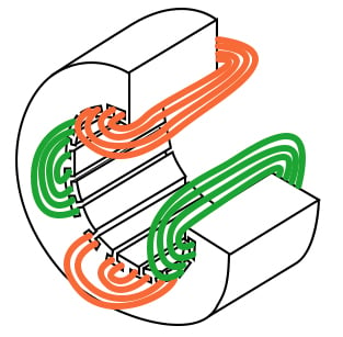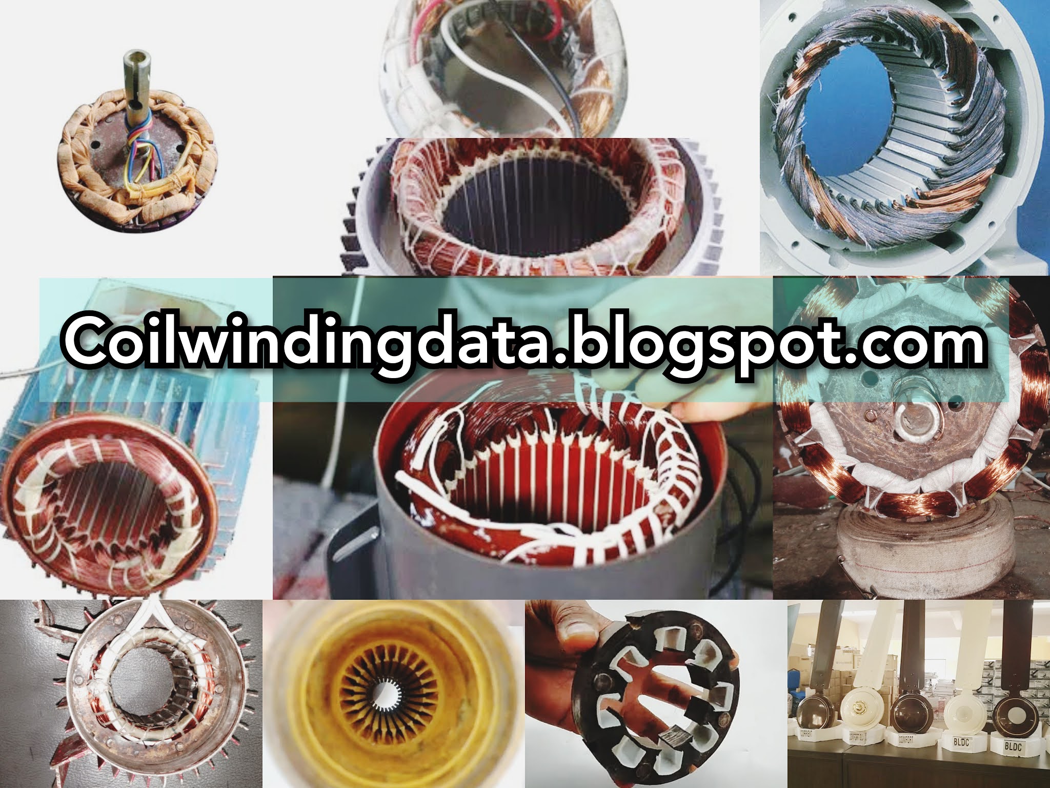


Moreover, the number of rods should not be equal to an integral multiple of the stator’s slots, as this may cause magnetic interlocking of both components. The rotor bars are slightly skewed to prevent them from locking against the gaps between the stator coils, ensuring a smooth and noise-free rotation. It gets its name from its cylindrical cage-like structure that consists of longitudinal conductive bars, made of aluminum or copper, short-circuited with the rings formed of the same material on both ends. Squirrel Cage RotorĪ squirrel-cage rotor is one of the most widely used rotors in induction motor manufacturing because of its exceptional characteristics, such as reliability, robustness, and low manufacturing cost. There are two types of rotors used in the manufacturing of induction motors. It is a cylindrical unit mounted on the shaft that carries the mechanical load. RotorĪ rotor is the rotatory part of an induction motor. The coil of the stator, also known as stator winding, is made of copper wires insulated with enamel, varnish, or resins, to avoid any short circuit. The laminated structure of the stator is employed to prevent eddy current and hysteresis losses that would otherwise occur with a solid core. It’s the stationary part with slots for the coil of the motor’s electromagnetic circuit to wind through.

The rotatory action of the shaft is carried out by arranging the following components in a particular manner.Īn induction motor’s stator is a hollow cylindrical core comprised of laminated and layered thin metal sheets.
INDUCTION MOTOR WINDING LICENSE
Open Access This is an open access article distributed under the CC BY-NC license ( ). The result showed that the proposed motor with 4 windings design had better performances than the conventional induction motor. The conventional single-phase induction motor used as a comparator was a single-phase induction motor of 220V, 8.3A, 4 poles, 1 HP, cage rotor, 1440 RPM, 50Hz. Performances of the proposed method were compared to the performances of a conventional single-phase induction motor that had the same construction of the stator, rotor and current rating. The auxiliary winding current of the motor was controlled by the Arduino control system. The windings current rating of the proposed motor was 2.74A and 3.15A for the main and auxiliary winding, respectively. The windings of the motor are divided in 4 groups, one winding act as the main winding and the other three windings act as the auxiliary windings. This study was focused to design a winding construction for capacitor-start capacitor-run induction motor. Because of that, this study was aimed to show a new design that simply by using 4 windings in the stator. The winding design was more complicated than the poly-phase induction motor. A single phase induction motor usually has two windings, the main and auxiliary windings.


 0 kommentar(er)
